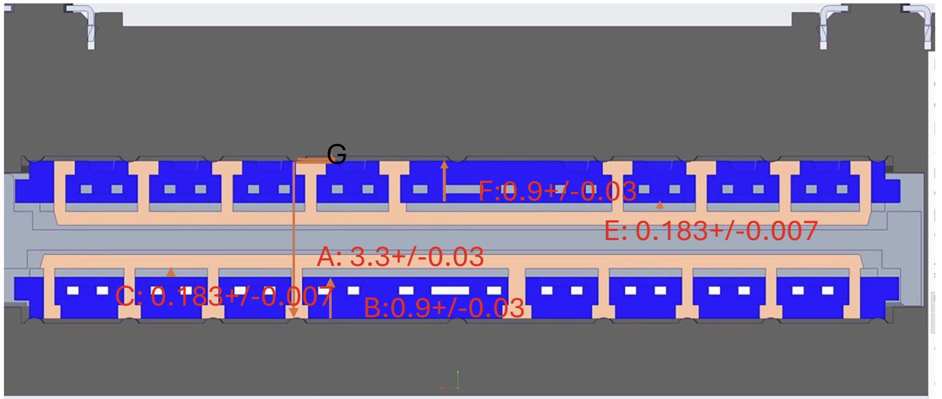
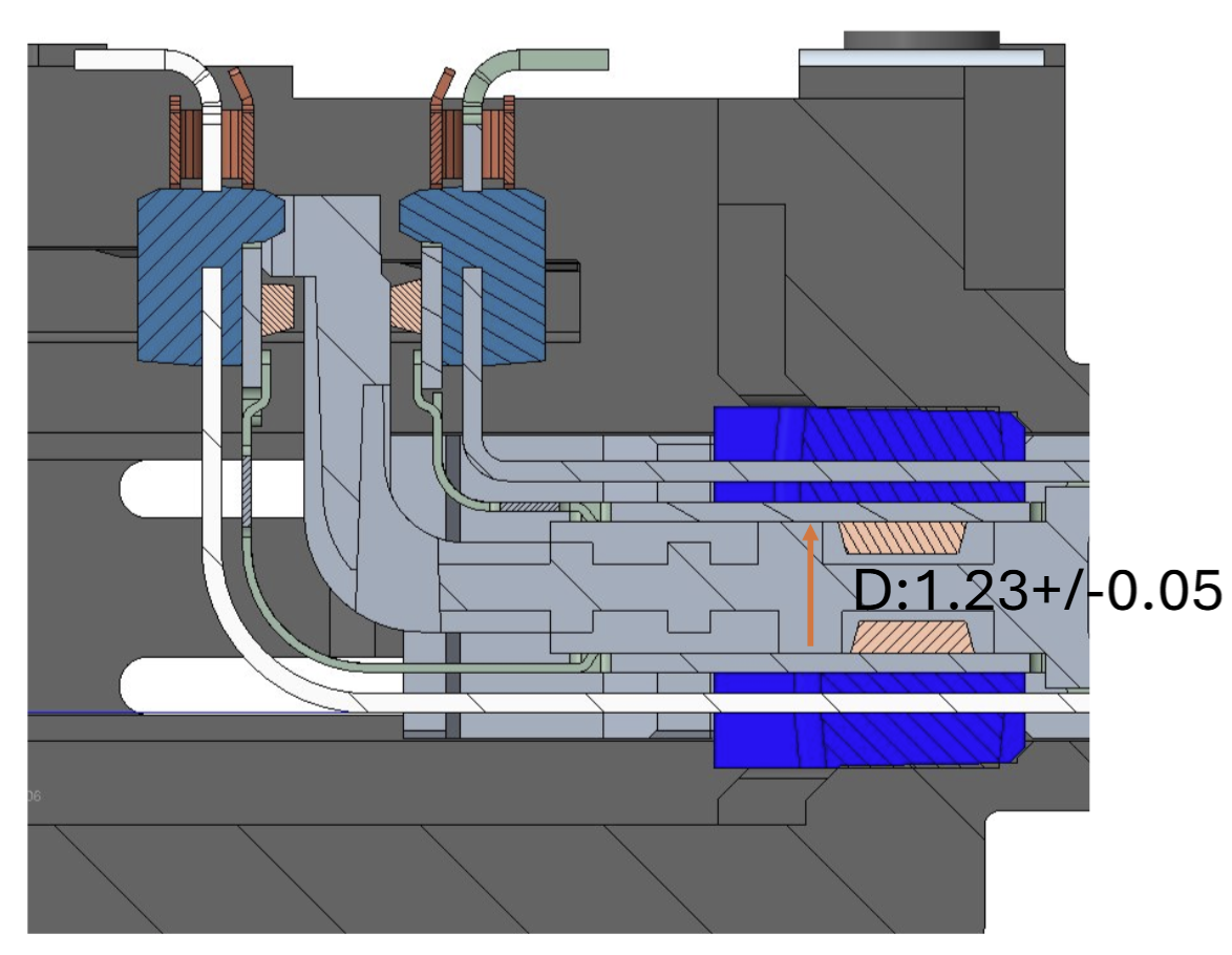
Case 1 · Interference
306 PPMCase bumps and overmold
Professional case study · Mechanical engineering internship
Selected work across high-speed connector product development, statistical tolerance analysis, precision fixtures, and manufacturing requirements at TE Connectivity.
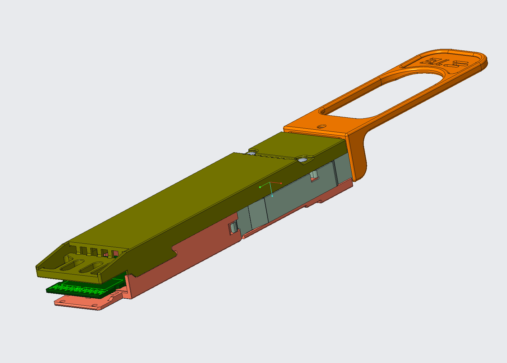
01 · Product development
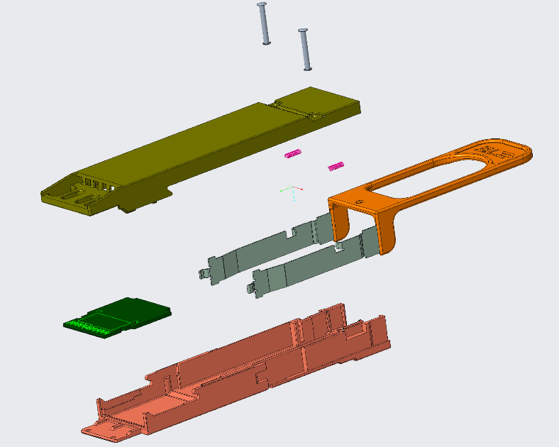
The project began as a concept that needed a complete mechanical definition before manufacturing could proceed. I developed the Creo assembly and exploded view, prepared a 2D drawing with GD&T, and worked through the documentation and compliance workflow required for preliminary release.
The work connected geometry, assembly intent, drawing control, part/document relationships, and manufacturing handoff rather than stopping at a CAD model.
02 · Statistical tolerancing
The analysis compared statistical and worst-case interpretations, then checked the numerical setup through hand calculations before the results were used in DFM/NPI discussions.
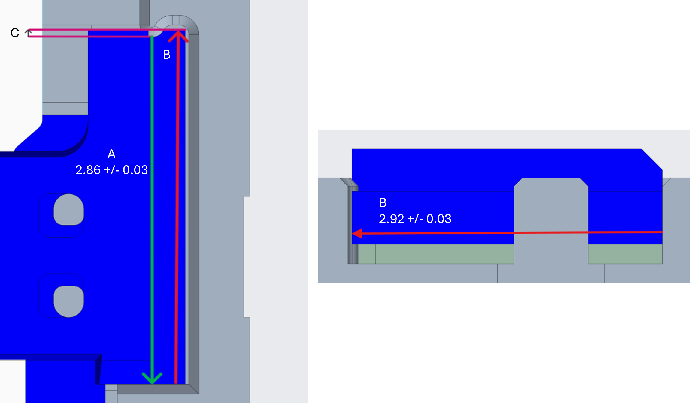
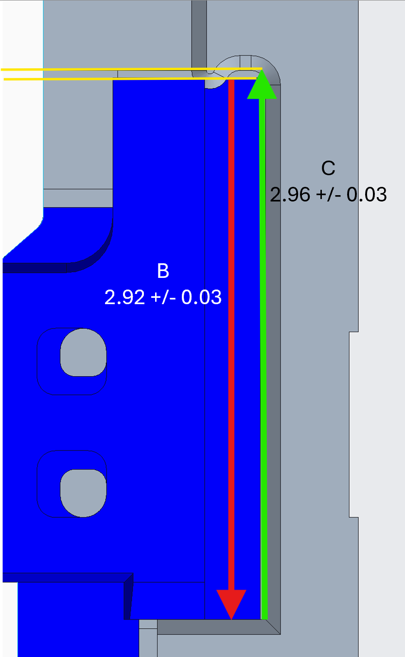
Case 1 and Case 2 produced low statistical failure estimates. Case 3 showed a higher probability of clearance between the organizer and overmold at the lower end of the distribution.
03 · Additional work
The internship also included connector design, fixture validation, automation requirements, and fixture redesign.
Connector design
Designed an organizer in Creo by adapting selected legacy components for a new connector direction. Planned follow-on work included casing changes, DFM, and signal-integrity simulation.
Intermediate design stagePhysical validation
Used microscope-assisted assembly and inspection to verify very small detent components, enabling continued assembly of the larger measurement fixture.
Subassembly verifiedRequirements engineering
Observed the manual process, spoke with operators, researched automation approaches, and translated the findings into mechanical, sensing, and HMI requirements for vendor quotation.
RFQ / vendor quotation stageFixture redesign
Defined modifications to the host-PCB models and base plate and planned clamp integration using Creo, 3D printing, and manufacturing methods.
Work in progress at presentation04 · Methods used
The internship work covered CAD, tolerances, drawings, release systems, manufacturing preparation, physical assembly, and vendor communication.